Controlling teleruptors using Apple Homekit

Let's say you want to start controlling and automating (part of) your teleruptor-equipped domestic electrical installation using Apple Homekit.
Before we dive into the technical details, let's first explain how a teleruptor-based system actually works and how it compares to a classic electrical system.
Adding smarts to a classic electrical system
In a "classic" electrical installation, the light switches are tightly-coupled (hard-wired) to the lights they control. This means there are wires going from your fusebox to your switches and from your switches to your lights. If you want to enable home automation for this kind of installation, you generally have 2 options:
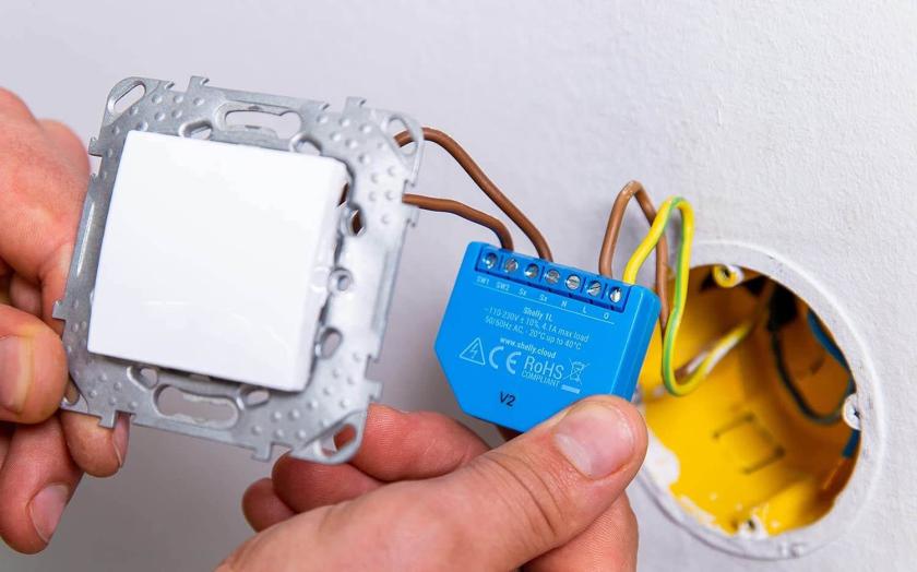
- Smart Wi-Fi switches to be built into your walls (a popular one being the Shelly 1L)
- Smart lightbulbs like the ones offered by Philips Hue
These are OK as a retrofit solution, but they have some important disadvantages:
- Scale: in the case of smart Wi-Fi switches, you need a separate Wi-Fi switch for every series of lights. In case of smart lightbulbs: you need to replace all your classic bulbs with smart bulbs
- Cost: the automation cost increases linearly when you add switches or bulbs. Next to that, if you are into the Apple ecosystem: Homekit-compatible smart gear tends to be more expensive compared to solutions designed to be compatible with Google Home or Amazon Alexa.
- Reliability: both solutions rely on wireless communication (Wi-Fi or other radio protocols like Zigbee), which are prone to dropped connections, bad wireless signal, etc.
- Complexity: some of these solutions require to install some sort of hub which bridges the wireless signals to ethernet. Each brand tends to have their own hub (e.g. the Hue Bridge). Luckily, Matter promises to streamline this landscape in the future. If you plan to buy into such a solution, look out for Matter-compatible gear.
- Usability: each brand ecosystem comes with its own app, meaning you need multiple apps on your phone to operate all your smart equipment. This makes things cumbersome to use and prevents proper automations across solutions from different brands.
Bottom line: retrofit solutions are fine if you are stuck with a classic electrical installation, but they are far from ideal. If your wiring is still to be done, you should look into a more modern wiring scheme.
The big boys in town
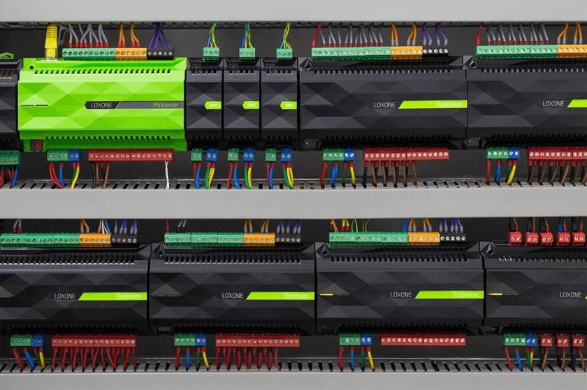
If you wired your house like 10 years ago, the domotica and home automation market was still very immature and expensive. Solutions like KNX, Niko Home Control or Loxone (see image below) have a wide range of capabilities, but are very expensive and lock you to a specific vendor (parts, maintenance, etc.). Moreover, you need a technical background to configure these solutions, set up automations, configure scenes, etc. In the end, you also don't want to throw this complexity over your family members in any case: if the software fails, you should still be able to operate all basic appliances by simple push buttons!
Future-proof wiring
What you are looking for is a decent wiring system which allows you to add home automation in the future once more simple and easy-to-use technology becomes available.
The key aspect here is that you never hardwire switches to electrical equipment. NEVER. This goes for lights, switched outlets, electric shades, shutters, your garage door engine, your door bell, etc. It might cost you a bit more on the wires, but this setup gives you all the flexibility you need in the future.
Enter teleruptors
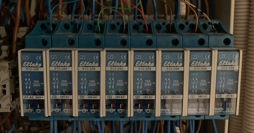
So how do you switch your lights when using a centralized wiring system? Somewhere, you need to hook up your light switches to your lights. A teleruptor does just that: it sits between the push-button wires and the light wires. Note that in this kind of system, your light switches are stateless, meaning they are essentially push-buttons (e.g. the Niko 170-70001, which can control 1 series of lights). When you operate a push-button, a low-voltage (often 24V) pulse is sent to the teleruptor. The teleruptor reacts to this pulse by flipping its state to allow electricity to flow or stop flowing to the associated lightbulb. A widely used solution is the Eltako S12-200 teleruptor, which is a basic bipolar teleruptor (see image below).
These teleruptors are installed in or near your central fusebox. This is exactly where you want to be, since you have 1 single place where you can throw in a software-based controller to trigger these teleruptors. So how do we get started? Remember, our goal here is to control certain light circuits using the Apple Homekit procotol.
In general, there are 2 solutions here:
- Swap (some of) your teleruptors with off-the-shelf smart relays (e.g. the Shelly Pro 1 or the Loxone system mentioned above)
- Build your own smart relay and put these parallel to your existing push buttons! 😁
For both of these solutions, keep in mind that your will need some sort of software-based "bridge" to make your relay(s) communicate with Apple Homekit. More on that later.
For this tutorial, we are only going to go into solution 2.
Hardware
Like mentioned above, the idea is to insert a smart relay in parallel to our existing push buttons. This means that the smart relay is on the same level as the push buttons and is pushing a 24V signal to the teleruptor, resulting in the latter to switch the light on or off. So our smart relay is only dealing with low-voltage electric flow, not with 230V.
As a foundation for our smart relay, I highly recommend to use a Raspberry Pi. It has a number of general purpose input/output (GPIO) pins, which we can use to drive a separate relay board. The Raspberry Pi 5 will be released soon, which is the one you want to get to get the latest chipset and features. For the relay board itself, there are various options available. I would suggest to go for a "HAT" solution (Hardware Attached on Top), since you don't need any intermediate breadboards or such. It mounts directly on the GPIO pins of the Pi. With this Raspberry Pi 8-Channel Relay Expansion Board, you will be able to drive 8 teleruptors / light circuits.
Wiring
Warning: do not mess with electronics if you don't know what you are doing. Always cut off the power from your circuits if you want to change things. Consult a professional in case of any doubt.
Let's wire things up:
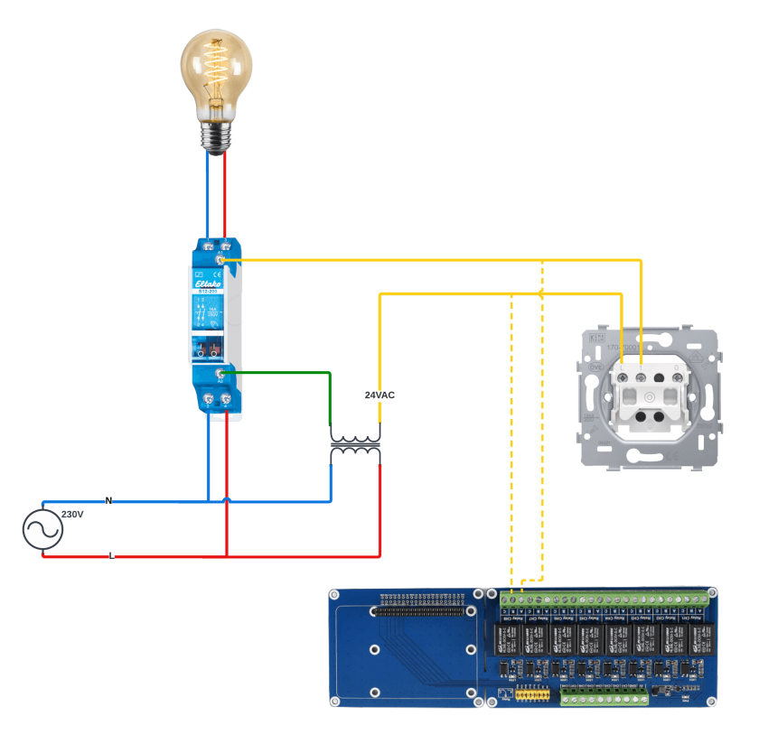
As you can see in the diagram above, we hook up our relay board parallel with our wall push button (yellow dotted lines). Adjust the wiring according to your type of push button, type of relay board and teleruptor type.
How does this circuit works? There are now 2 ways to trigger our teleruptor:
- When the push button is pushed and released
- When the respective relay on our relay board is opened and closed again
In both of these cases, a 24V signal is passed to the teleruptor which in turn changes its state and turns the light on or off.
These type of teleruptors are build to be triggered by a human manually pushing a button. This action takes around 200ms. So what we need to do now is ensuring the respective relay on our relay board closes the circuit for around 200ms and then opens up again. To do this, we will write a small script on our Raspberry Pi.
Software
OK, back to our end-goal for second: making sure we can use Homekit to trigger our teleruptors. A key software ingredient to make this possible is the wonderful Homebridge package.
Homebridge is a lightweight NodeJS server you can run on your home network that emulates the iOS HomeKit API. It supports Plugins, which are community-contributed modules that provide a basic bridge from HomeKit to various 3rd-party APIs provided by manufacturers of "smart home" devices.
To get started with Homebridge, install Raspberry Pi OS on your Raspberry Pi or go for the off-the-shelf Homebridge image for Raspberry Pi.
Next, we need a special Homebridge plugin to trigger our relay board. We will rely on the omnivalent Script2 plugin for this. This fantastic plugin allows you to execute any script when you operate a Homekit accessory and write the state of this accessory to disk. This is beautifully simple and it even allows for the correct accessory states to be recovered after a power failure! You can add this plugin using the Homebridge UI.
Now we are ready to start playing with the GPIO pins and make our relay board do what we want. Check out the official documentation if you want to learn the details of the GPIO header.
In essence, we will use a custom Python script for this. This script gets called by the Script2 plugin and does mainly 2 things:
- Trigger a certain relay on the relay board, depending on which pin you pass as a parameter to the script
- Set or remove the flags which indicate the teleruptor state (files on disk)
To use this script, place it in a separate directory in your home directory. Make sure this file is executable using the chmod command. Also create an empty "flags" directory. Make sure this directory is writable (also using the chmod command).
$ mv hb_script2_gpio.py /home/@user@/homebridge_script2/
$ mkdir /home/@user@/homebridge_script2/flags
$ chmod +x /home/@user@/homebridge_script2/hb_script2_gpio.py
$ chmod -R 700 /home/@user@/homebridge_script2/flags
Finally, install the rpi.gpio package to be able to communicate with the GPIO pins from within the Python script:
$ sudo apt-get install rpi.gpio
Now you should be able to do the first test of your setup! Run the following command with the correct pin number (check out the GPIO documentation and the documentation for your relay board to find out which pin to trigger, corresponding to the relay hooked up to your teleruptor)
$ /home/@user@/homebridge_script2/hb_script2_gpio.py @pin@ on
$ /home/@user@/homebridge_script2/hb_script2_gpio.py @pin@ off
When running these commands, you should hear a click sound from the corresponding relay on your relay board. Furthermore, you should see a flag appearing/disappearing in your flags directory.
To finish things off, we should add our teleruptor as an accessory to our Script2 plugin config. You can omit the state, on_value and unique_serial parameters:
"accessories": [
  {
    "accessory": "Script2",
    "name": "Light 1",
    "on": "/home/@user@/homebridge_script2/hb_script2_gpio.py @pin@ on",
    "off": "/home/@user@/homebridge_script2/hb_script2_gpio.py @pin@ off",
    "fileState": "/home/@user@/homebridge_script2/flags/pin_@pin@.flag"
  }
]
Finally, add your Homebridge system to the Apple Home app.
You should now see your accessories pop up, as defined in your Script2 plugin configuration. Tap the icon in the Home app and your connected light should turn on!
Important note: when you push the button, the state of the light will obviously not be updated in the Home app. The idea is to have the push button still available in case of problems with your Pi. However, you should not use it when working with the Home app. This setup is ideal for lights which are mainly triggered by Homekit automations.